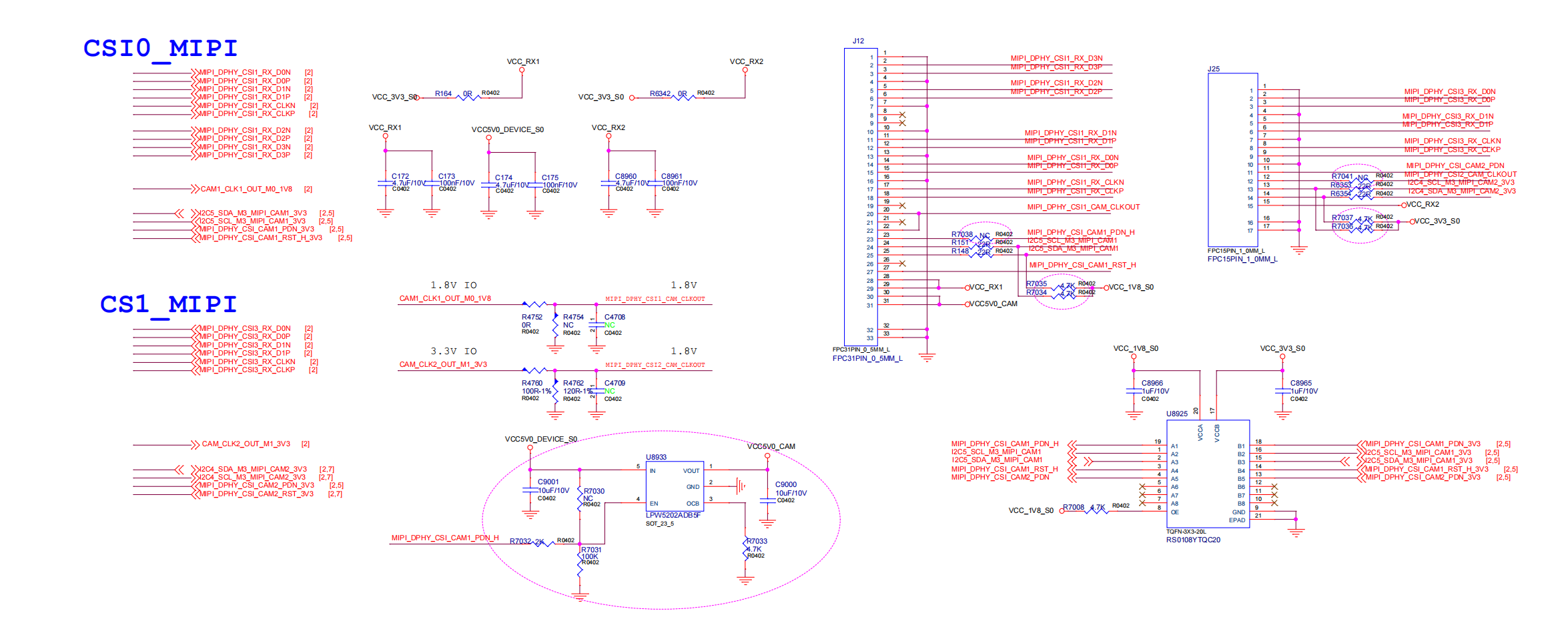
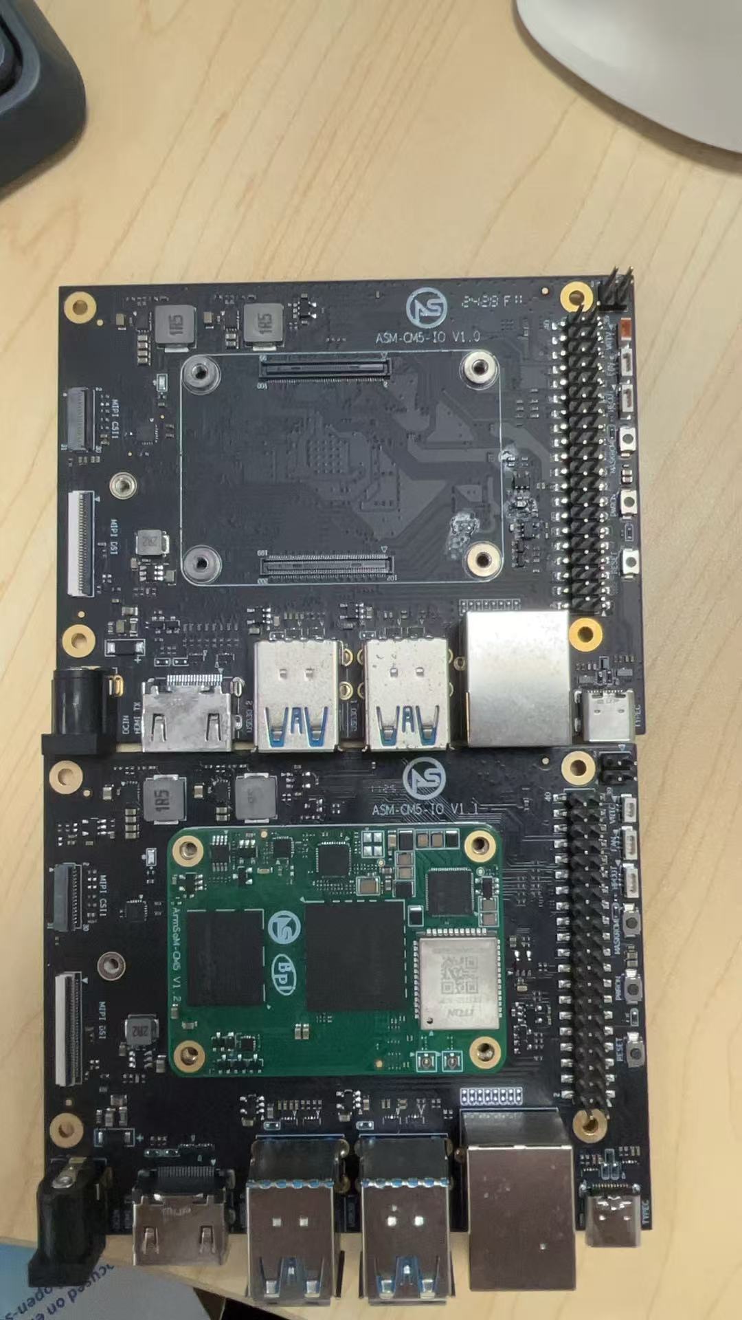
Thе U8933 needed to install? The chip is missing from the photo of the board, but it is on the circuit diagram and in the component placement file.
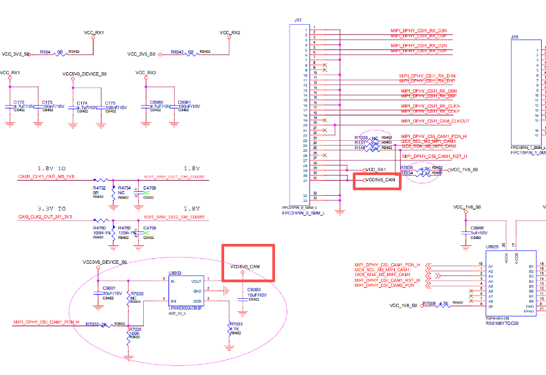
if this chip is not installed, where should VCC5V0_CAM be connected?
MIPI_DPHY_CSI_CAM1_PDN_H is not connected to anything?
Hello, no separate installation is required. Do you have a picture of the actual product? The photo is of our initial test version, used for promotional purposes. The actual product sold will be based on the schematic diagram, as shown below.
Are you adjusting it to 4 lines or 2 lines?
The camera J12 requires this chip
NC blank patch, there is an internal pull-up feature in the PDN camera, no need to control it again
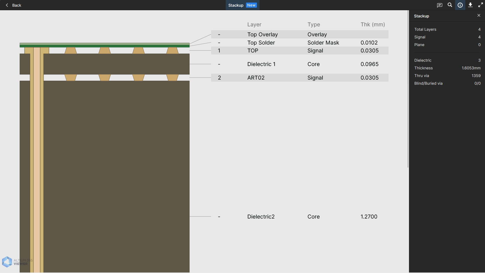
Hello, i looked pcb stackup in altium viewer(allegro is not avalable for me), and there show me 3 numbers of core(no one prepreg) and quite non-standard sizes.
Can you please provide me information about the layers stackup and the width of the tracks, the width between tracks in a diff pair (mipi-csi, usb otg) and the sizes of vias.
I want to make the board as close as possible to the original in order to avoid errors in the impedance of the diff pairs for the camera and usb.
Very grateful if you provide this information